
See also:
Basic Deliverables from Oil & Gas Engineering Design
In commencing design for an industrial facility, the process flow determines the type of facility. The list of equipment utilised in plant units for oil & gas, and power plant varies between them. Thus, facility requirements reveals which materials are to be installed. In standard plant engineering, the 3 primary deliverables for this design stage are the: process flow drawing (PFD), general arrangement drawing (GAD) and single line drawing (SLD).
A necessary step towards obtaining these deliverable documents is the process flow design.
Considerations for Process Flow Design
Several considerations are made during the process flow design. These details often emanate from the various engineering disciplines on the project. Usually chemical, petroleum, mechanical and electrical engineers. They provide useful information which are employed in establishing processing units. The type of fluid as well as input and output conditions when it interacts with the various stages of production. Conditions which include temperature, pressure, purity and other flow and constituent characteristics.
One important principle that ensures a balance from start to end of the process flow is conservation of mass. From this law the variable, mass flow rate, is derived and forms the basis for several calculations. All considerations are meant to establish an acceptable process flow that considers engineering, safety, functionality and efficiency.
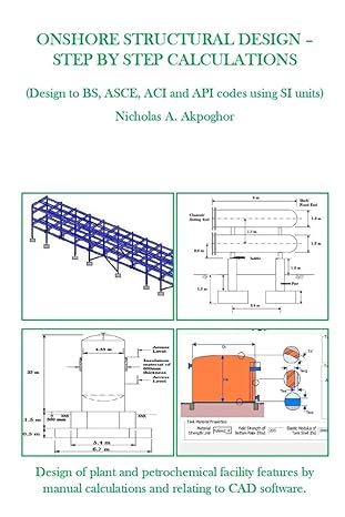
A simplified collection of calculations for onshore structures can be obtained from here: https://www.amazon.com/ONSHORE-STRUCTURAL-DESIGN-STEP-CALCULATIONS/dp/B08Z3QPNP5
Also available in Nigeria for: ₦18,500.00 Contact – +2348182035528
Udemy course: Onshore Structural Design – Step by Step Calculations | Udemy
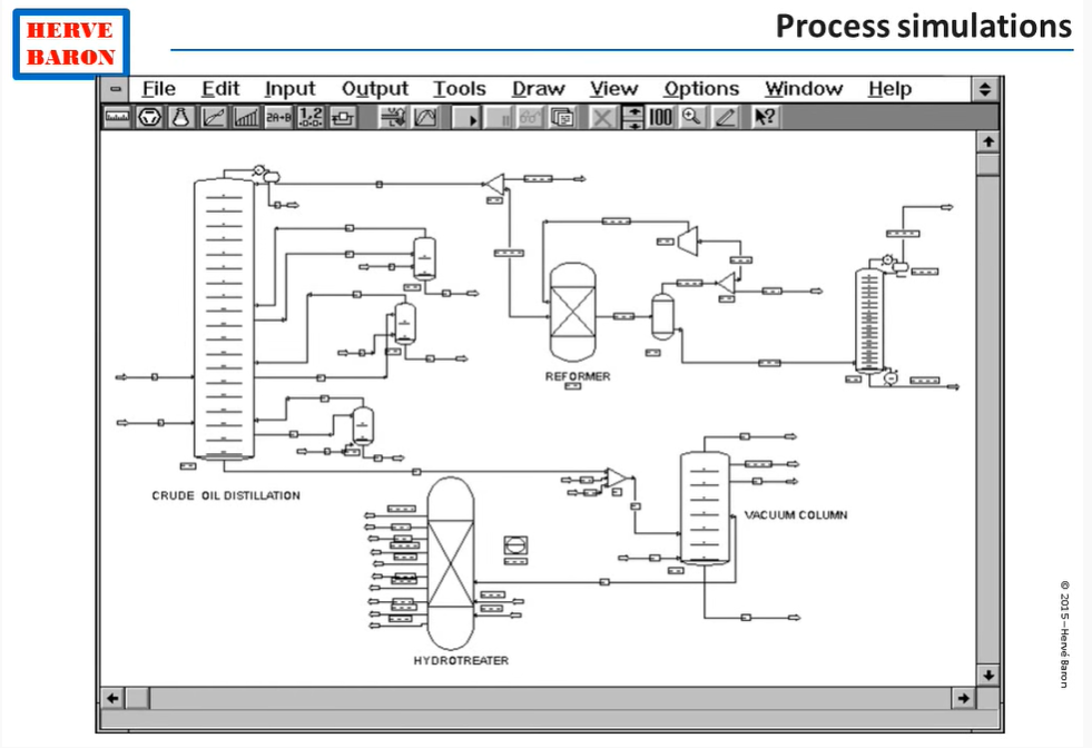
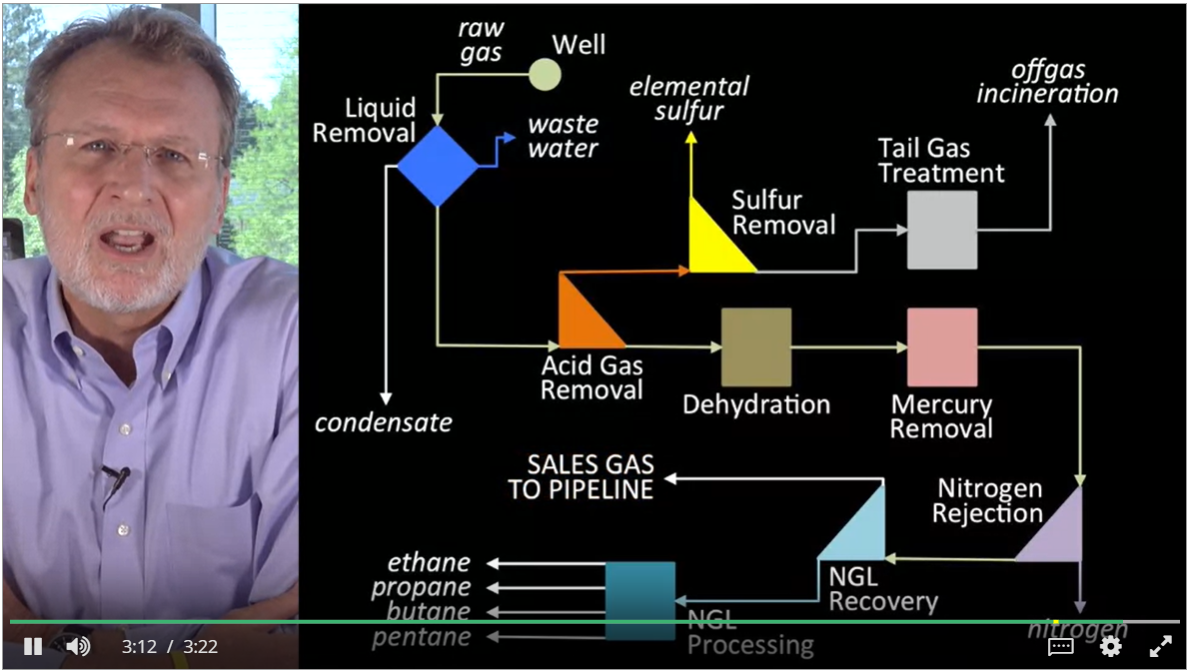
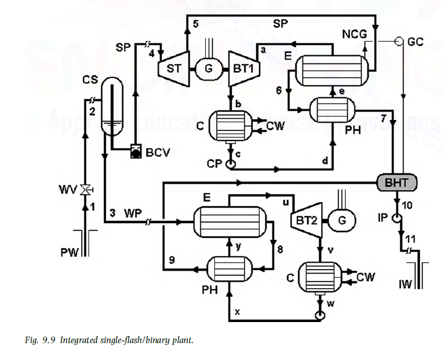
PFD for Various Plant Types
Below are sample PFD’s for various plant types.
See video for all references.

[…] Oil & Gas, Power Plant and Industrial Facilities Engineering – Part 2 […]
[…] Oil & Gas, Power Plant and Industrial Facilities Engineering – Part 2 | Process Flow Desig… […]
[…] Oil & Gas, Power Plant and Industrial Facilities Engineering – Part 2 | Process Flow Desig… […]